Tag Archive for: power module

Gruppo PBM, a leader in industrial battery chargers, is using SiC MOSFETs in its new HF9 battery charger family to enable higher efficiency and power density at a lower overall system cost.

Demand for safe, efficient and fast-charging industrial batteries has increased exponentially along with the proliferation of power electronics. The HF9 product family is designed to provide the highest possible efficiency while achieving easy scalability for power ranging from six to 16 kilowatts. These benefits are made possible in part by Wolfspeed 1200V SiC MOSFET technology.

“We selected Wolfspeed SiC Planar MOSFETs for our new HF9 battery charger family because they enabled us to improve our battery chargers while achieving operational savings, increased productivity and increased safety. This was not possible with the best IGBTs in the market,”

said both Marco Mazzanti and Giancarlo Ceo, who respectively serve as CTO and R&D Engineer at Gruppo PBM.

Based in Italy, Gruppo PBM specializes in rugged high-frequency battery chargers, dischargers and testers. By using Wolfspeed SiC MOSFETs in its latest HF9 family, Gruppo PBM not only achieves improved efficiency, but also a reduction in component count, improving the overall reliability in the system by lowering the operating temperatures and—most importantly—reducing overall system cost.

“Wolfspeed’s SiC MOSFETs, especially our new C3M 900V family, are enjoying rapid adoption in the growing battery charger market segment,” explained Edgar Ayerbe, Wolfspeed’s power MOSFET marketing manager. “Our products increase power density and dramatically lower switching losses, making it possible to introduce smaller, cooler and lower cost chargers for the automotive and industrial markets.”

Sourcehttp://www.wolfspeed.com/news/gruppo-pbm

Game changing new technology delivers bi-directional AC/DC power flows, combining the functions of a rectifier, an inverter and a transfer technology in a single module.

Eltek is today announcing the launch of the Rectiverter, a power conversion module combining the functions of a rectifier, an inverter and a “static transfer switch” in one. The Rectiverter is a 3-port bidirectional converter that simplifies solutions providing both AC and DC power to critical loads in telecom, data center and industrial applications. It features a power conversion efficiency of 96% in mains mode and 94% when operating as an inverter.
Combining a rectifier, which converts AC to DC, and an inverter, which converts DC to AC into one box simplifies the power system complexity, reduces system size and improves overall system reliability, resulting in a reduced total cost of ownership over the product lifetime.

Eltek’s first product on the market is the Rectiverter HE, delivering 230V/1500W AC and 48V/1200W DC. It features high power conversion efficiency, and is controlled by a single Eltek Smartpack controller. Rectiverter systems are available as single or 3 phase, input and output, and can be scaled to meet any power demand.

“The Rectiverter is the first new technology development in modular power conversion for many years and it’s a big step into more efficient, more reliable power infrastructure,”

said Morten Schoyen, chief marketing officer of Eltek.

“It is a product that fits in well in applications where we today use rectifiers and inverters separately, and will open doors to new exciting opportunities”

“To integrate a rectifier and an Inverter in the same box, with bidirectional power flow and still maintain high efficiency is an impressive achievement,” said Dr. Tore M. Undeland, Prof Emeritus of Electrical Engineering at Norwegian University of Science and Technology (NTNU).
The Rectiverter first version is based on 48VDC and has a maximum capacity of 1500 VA for AC and 1200W of DC.  The total capacity of a module is 2000VA (AC and DC combined).

Source

There was a time when consumer electronics innovations were the adaptation of Government’s and institution’s technology needs, into cheaper home sized devices, like microwave oven or flat screen TV.

Now some technology makers are still trying to renew those old saturated markets with some innovation (like TV market, which failed in selling us 3D and now tries very hard with 4K…), but mostly innovations are now pushed by our everyday – new – needs. Technologies  that are born to make people’s lives easier (healthier, more comfortable, more connected…) led  us to wear and use electronics to measure, help and assist us. That’s what you see when going down the Consumer Electronics Show (CES) alleys in Las Vegas.

Of course, that’s what we love! Cause electronics means power. So it means power electronics. You’ll tell us we see power electronics everywhere… But it is everywhere! Especially at CES 2016. Yes, all our electronics still need batteries…

Electric cars crashing the party at CES

Faraday future electric car prototype concept car

Faraday Future Concept car presented at CES 2016


They took all the space to showcase nothing really new: Faraday Future managed to make the buzz on a concept car, but nothing ready to produce. Tesla and all others like Ford, GM or Chevrolet showed either their EV cars or some autonomous capabilities.

Capabilities which will not be available before 2017 or 2018 for all of us. That’s kind of crashing the party, don’t you think?

Smaller is the new better (for Power electronics)

Innergie ICE 65W laptop adapter - from Delta - Laptop power supply

Innergie ICE 65W laptop adapter – from Delta

We cannot talk about this year’s CES without citing (again) FINSix. The maker of the Dart, claimed to be the smallest laptop charger in the world signed an agreement with Lenovo. Their technology will included in an optional charger for Lenovo latest high-end netbooks. It also seems that Kickstarter’s preorders are close to delivery. We, at Point The Gap, ordered the competing Zolt, from Avogy. We already received it but hesitate to tear it apart to see the inside…

Note that Delta released also a tiny power supply for laptops. It’s called Innergie ice and it’s a 65W, and it looks a lot like FINSix Dart.

Fuel cell are making their way

MyFC showed their small Fuel Cell battery for smartphones. They provide also 2USD cartridges with the 99USD charger that provides 1,800mAh. Enough to charge up most smartphones for a day.

Japan based Aqua Power Systems also presented a USB charger based Fuel Cell technology. It can charge a smartphone up to 20 times before you need to replace the magnesium plates. It can provide up to 30,000mAh from 6-10% salt water.

Do you take your battery with salt or sugar?

Presented at CES, and probably a must have of 2017 or 2018 CES will be lithium-free batteries. You know that Lithium is a limited resource on earth. It costs a lot to the environment. So having another element in our batteries would help us save the Earth.

PDP presented a battery pack for video game controllers using « a physical reaction rather than a chemical reaction » to charge in one minute. We can’t wait to know more about it.

During CES, I found two news about the next type of batteries. The first from CEA in France, and replacing Lithium with… Sodium. It’s not a new technology (known since the 60’s) but with lithium lack and prices, I bet it will raise in interest. Another one came from a Chinese PhD students team which managed to get current out from Sugar and bacteria. It’s not as advanced but still interesting.

Wireless power is the wow thing this year!

Wireless power is the new hype. And we’re checking if it’s worth making a market report about it by the way. Vote here if you want to see a “Market and technologies enabling Wireless power” released!

We have followed the GaN devices maker EPC Corp. tweets and news to know where were wireless power devices hidden ;-)

The biggest were there: Energous, Ossia, WiTricity,Cota, the Wireless Power Consortium…

The interesting fact about this technology is not really that it can help power your mobile phone on a table or ditch the laptop adapter. It can power all the small intelligent objects we see everywhere, and that cannot handle more than a day of life: imagine putting back your « smart sport shoes » on their charging support, with no wire to not compromise the waterproof. Same with your watch, headphones, or all the wearables technologies or small smart objects like ibeacons, tags, etc. That is, from our point of view, the real market for wireless charging.

The technology is here, ready for integration.

The new facility produces and develops Insulated Gate Bipolar Transistor (IGBT) modules, which are terminal power semiconductor devices used as electronic switches that combine high efficiency and fast switching, IMI said in a statement.

They are used on trains, refrigerators, lamp ballasts, air-conditioners, solar applications, motion devices and anything that needs electric switching and requires power efficiency.


“The power module business is very much aligned with IMI’s strategy of offering innovative solutions which will impact our top and bottom lines. Further, it is in line with the expanding business in our target markets of automotive and industrial segments,” IMI President and Chief Executive Officer Arthur Tan was quoted in the statement as saying.

IMI is one of the few companies in the world capable of handling not only the electronics manufacturing side of the power modules but also the power semiconductor side of the business, Mr. Tan said.

Power modules are seen accounting for 30% of the total power of semiconductor market by 2019, IMI said.

Demand for modular power solutions from original equipment manufacturers is on the rise because of their higher power density and reliability, IMI said.

The company refurbished a surface mount technology assembly facility in Laguna Technopark into a power module facility, IMI Strategic Planning and Marketing Manager Frederick L. Blancas said.

IMI reported a 5% year-on-year jump in nine-month profit to $22 million despite a global economic slowdown and electronics industry downturn that pulled down consolidated revenues by 4% to $621.5 million.

Shares in IMI added four centavos or 0.69% to close at P5.80 each on Thursday.

Source

GaN Systems, the manufacturer of gallium nitride power transistors, announces that its foundry, Taiwan Semiconductor Manufacturing Corporation (TMSC), has expanded the volume production of products based on GaN System’s Island Technology® by 10X in response to demand from consumer and enterprise customers.

GaN Systems has the industry’s broadest and most comprehensive portfolio of GaN power transistors with both 100V and 650V GaN FETs shipping in volume.

The unique combination of TSMC’s gallium nitride process and GaN Systems’ proprietary Island Technology design is further enhanced by GaNPX™ packaging, which delivers high current handling, extremely low inductance and exceptional thermal performance. GaN Systems’ power switching transistors continue to lead the gallium nitride market, providing best-in-class 100V and 650V devices and driving product innovation ranging from thinner TVs to extended range electric vehicles. Sajiv Dalal, VP Business Management at TSMC, comments,

“We are delighted to confirm that our collaboration with GaN Systems has brought the promise of gallium nitride from concept through reliability testing and on to volume production.” Adds Girvan Patterson, GaN Systems’ President,

“GaN has emerged as the power semiconductor solution of choice. Smart mobile devices, slim TVs, games consoles, automotive systems and other mass volume items have been designed with GaN transistors as the enabling power technology, so it is imperative that devices are available in correspondingly large quantities. That is why, after three years of working together, we are so excited to formally announce our collaboration with TSMC.”

Using Island Technology with TSMC’s GaN-on-Silicon manufacturing techniques enabled GaN Systems to deliver the most usable, high performance, normally-off transistor to the market in mid-2014. This has allowed global power system manufacturers in the energy storage, enterprise and consumer markets to design, develop, test and bring to market more powerful, lighter and far smaller new products in their quest to attain competitive edge. To meet customers’ increasing demand for high GaN volumes in 2016, TSMC’s commitment to volume production flow comes at the perfect time.

Check our GaN Market report to know more about GaN Systems and their potential

Rohm has recently announced the development of a 1200V/300A full SiC power module designed for inverters and converters in solar power conditioners and industrial equipment.

The high 300A rated current makes the BSM300D12P2E001 suitable for high power applications such as large-capacity power supplies for industrial equipment, while 77% lower switching loss vs. conventional IGBT modules enables high-frequency operation, contributing to smaller cooling countermeasures and peripheral components.

In March 2012, ROHM began mass production of the world’s first full SiC power module with an integrated power semiconductor element composed entirely of silicon carbide. In addition, its 120A and 180A/1200V products continue to see increased adoption in the industrial and power sectors. And although further increases in current are possible due to energy-saving effects, in order to maximize the high-speed switching capability of SiC products, an entirely new package design is needed that can minimize the effects of surge voltage during switching, which can become particularly problematic at higher currents.

In response, the BSM300D12P2E001 features an optimized chip layout and module construction that significantly reduces internal inductance, suppressing surge voltage while enabling support for higher current operation up to 300A. And going forward, ROHM will continue to strengthen its lineup by developing products compatible with larger currents by incorporating SiC devices utilizing high voltage modules and trench configurations.

Key Features
1. Reduced switching loss through higher frequency operation
Replacing IGBT modules is expected to reduce switching loss by up to 77%, enabling smaller cooling systems to be used. And higher frequency switching will make it possible to decrease the size of peripheral components such as the coil and capacitors, improving efficiency while contributing to greater end-product miniaturization

2. Lower inductance improves current-handling capability
Increasing the rated current for power modules involves reducing the internal inductance to counter the higher surge voltages generated during switching. The BSM300D12P2E001 features an all-SiC construction and optimized circuit layout that cuts internal inductance by half, making it possible to increase the rated current to 300A.

Device Characteristics

  • Full SiC module integrates an SiC SBD and SiC-MOSFET into a single package
  • Equivalent package size as standard IGBT modules
  • Built-in thermistor
  • Tjmax=175 degrees C

Toyota Motor Corp disclosed the technique used to reduce the size of the power control unit (PCU) of the new (fourth-generation) Prius.

The PCU is used to control the electric power of the hybrid system and equipped with an inverter for driving the motor, a step-down DC-DC converter, etc.

The most distinguishing feature of the PCU is that its volume (8.2L) is about 67% that of the PCU of the third-generation Prius (12.6L). The small volume was realized by making improvements to the power device and cooling structure. Because of its smaller size, it can be installed right above the transaxle. As a result, it became possible to move the “12V battery” from the luggage space to the engine room.

To reduce the volume, Toyota changed the cooling method for a card-like thin power module called “power card.” The size of the power card was reduced by cooling the card from both sides to improve cooling performance and reducing the size of the IGBT chip (compared with the third-generation Prius). In the third-generation Prius, only one side of its power card is cooled.

Prius 4 Toyota power electronics converter

‘2-in-1’ product employed

The method of cooling both sides of the power card was also employed for the Lexus LS600h/LS600hL, which was released in 2007. At that time, it was a ‘1-in-1’ power card equipped with the power elements (IGBTs and diodes) of the power converter’s high or low sides.

For the fourth-generation Prius, Toyota adopted a so-called “2-in-1” package equipped with the power elements of the high and low sides to eliminate the space necessary to install the power card. The company newly developed a package of the power card for the fourth-generation Prius.

Toyota also reduced the loss of the IGBT. By reducing switching loss and steady loss, the company cut the power loss of the IGBT by about 20%, compared with the third-generation Prius. Though its withstand voltage is 1,200V, which is the same as in the case of the third-generation Prius. Its current density was improved by reducing the size of the chip. It is manufactured at Toyota’s Hirose Plant.

Number of control boards reduced to 1

To reduce the volume of the PCU, Toyota reduced the number of control boards inside the PCU from two to one by adding various functions to the driver IC of the power device. Furthermore, the company reduced the sizes of the smoothing capacitor and reactor as well as the thickness of the DC-DC converter.


Source: Nikkei Tech

I recently had the chance to test drive a Tesla. Not like any Tesla, the super-powered one: S85PD.

The one that has an “Insane” mode and can beat a Ferrari at traffic lights. Even though there was no Ferrari at the traffic light we stopped at, I can trust the fact that it can compete with many supercars.

And as a power electronics market analyst, I had to ask the sale guy about inverter and power modules. He did not know much about that. It’s not really his job, and he is not a design engineer. He knew a lot about the car and its features (which is enough to sell it) but not about the inside of the inverter, the power train, or the car…

So I asked Siri Google, and I had answers. I ended up on a Tesla car owners forum. I looked into it, and I found pictures and description of the inverter. Like the the picture down here.

Fig.1: 2×14 IGBTs in parallel is one leg of inverter—All packaged in discrete TO247 – From Tesla Roadster and Model S inverter

All about Tesla and power semiconductor packaging

That’s the truth. Don’t go for a reverse engineering on a Tesla inverter. Engineers just made an awesome car with very simple off-the-shelf products. Do not look for any highly special package for power modules International Rectifier (now-Infineon) would have made specially for Elon Musk (just because he is Elon Musk). There is no such thing. The inverter is made of TO-247 packages (Figure 1), derived from TO-220 in the 1990’s in order to handle more power and heat.

They used 20-year-old power module packaging technology to build the fastest electric luxury car on earth. It’s that simple.

I was shocked again! (The first shock was experiencing the acceleration of “Insane” mode.) I wanted to share that with someone. So I went on the internet and asked a very dumb question on the Power electronics group of LinkedIn.

A question that sounded like that:

Linkedinquestion

And many comments, questions and reactions (and “likes”. There are “likes” in LinkedIn too… But you cannot “poke” anyone. I wish we had that feature).

And for those of us who are not hanging out in this virtual professional world of LinkedIn, I wanted to summarize discussions here.

What you get from these discussions

1. “Module or discrete?” is still a 2015 question.

The first power module packaging design question is to know if you are going to use a power module or not. And that is a question that Tesla engineers had to ask themselves and that JB Straubel, CTO of Tesla, asked himself designing the model S. He talked about it during 2010 APEC conference, and I wish I was there :-(

But according to the attendees, the choice of going for TO-series package rather than well-marketed EV series of power modules were:

  1. Simplicity of assembly
  2. Heat dissipation (and thus easy cooling)

Which is in total accordance to any engineer mind designing a product to:

  1. Work
  2. Be efficient

As the rest of the design is not engineering work … most of the time.

2. Power modules & IGBT packaging preconception

Most comments agree on the fact that a power module is a great thing, with a lot of room for innovation and many great features.

But they also agree on the fact that there are other factors to think about, when going for a design in power electronics, depending on the applications.

You still need to think about:

  • Volumes of production
  • Total cost of the solutions
  • Heat spreading and cooling requirements
  • Peak currents, ripples and other EMC stuffs
  • Size

Still you have interesting feedback putting down some preconception on power modules:

  • “The TO series are indeed very tough little beasts and I have been told by a senior semiconductor reliability engineer in some ways more reliable than a module, with respect to bond wires. Not something they usually advertise as the same company also makes modules targeted at EV/HEV”
  • “The TO-series package are really quite outstanding and I’ve used them a lot”
  • “That design allows Tesla to ‘insanely’ run 1500A through the inverter IGBTs and then the motor”

3. Theories on why Tesla made unexpected IGBT packaging choices

For most of the participants in the discussion, the choice of TO-247 totally made sense, but not always for the same reasons:

It could be because:

  • “The design was done when they were not sure about the volumes”
  • “There was no suitable module available at that time” (then what about today?)
  • “They wanted to reduce the risk of failure for this new product”

The point is not actually to try to find the right one, but to think about it.

We are in 2015, and we still find so many reasons why discrete TO-247 packaging could be a very good choice.
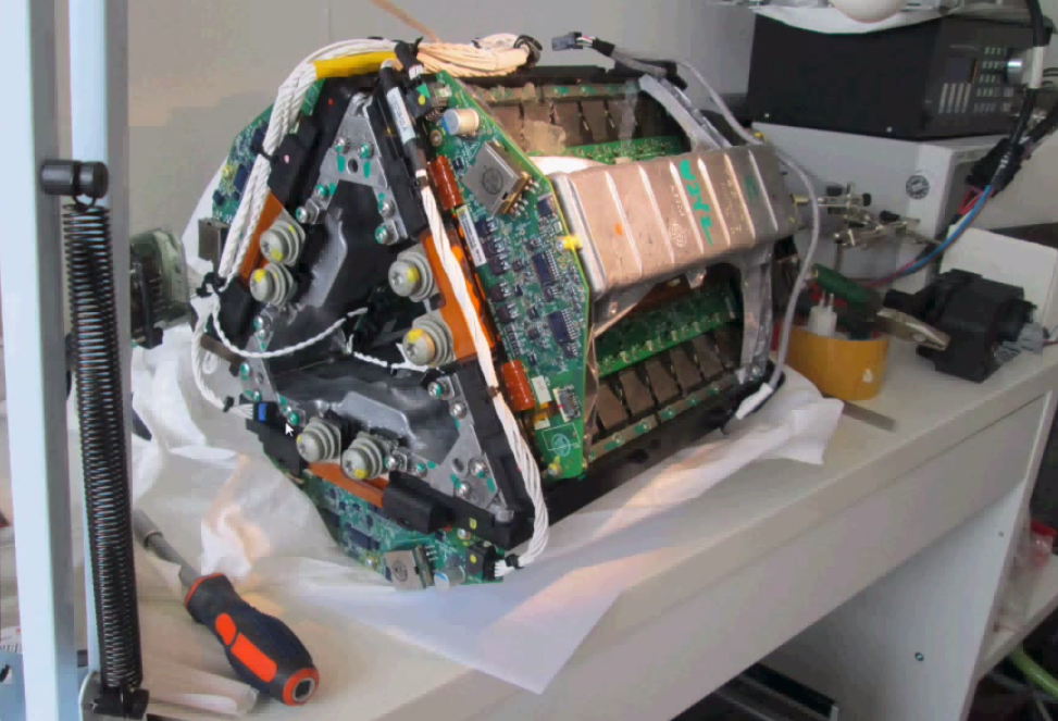
Tesla Model S inverter

Tesla Model S inverter – 3 phase represented by the triangle, having each two switches of 14 IGBTS in parallel

4. Power module packaging for EV/HEV—What’s next?

The state of the art and what would be the best choice in the future has also been discussed.

An interesting comment points out that:

the state of the art in power device packaging […] will most probably be in the higher volume, mass manufactured electric vehicles—from Ford, Toyota, GM, etc., There are definitely higher performance packages—with better characteristics in terms of thermal, inductance, tolerance to vibration, etc.

or that:

Tesla might not have the volume to drive custom power electronics packaging.

Which totally makes sense and proves that Toyota has a huge knowledge of how to build a power converter and hybrid car. They started Prius back in 1994 and have all the feedback and experience since then. On the other side, and that is Point The Gap comment: Is power electronics for Hybrid cars and Power electronics for full electric cars the same thing?

You get rid of a lot of constraints, starting with space and cooling restrictions when you design for a full electric car. (e.g.: Tesla’s cars have a rear and front trunk, with batteries under the car and inverters/motor group not taking much space).

4.1 .XT, SKiN and other IGBT packaging innovations

There is also a reminiscence of .XT Technology (Infineon) and SkiN (Semikron). These two technologies have been in one of our articles about PCIM 2015.

From Point The Gap point of view, these are all very interesting innovations. It’s just that they have been presented 2 to 4 years ago, and we are still waiting for available products. Remember the marketing campaign from Semikron in 2013 about SKiN technology. According to them, it may be ready in 2016. Why so much communication 3 years before availability…

And finishing with something that sounds very true to us:

“According to Tesla’s website the Power Electronics Module uses 84 IGBTs to power the 3-phase induction motor, or 14 IGBTs in parallel per switch. Is it the best solution? I seriously doubt it, although it may be the ‘lowest cost’ solution based solely on the bill of materials.”

4.2 Is best power semiconductor packaging “no-packaging”?

A parallel discussion also emerged on discrete packaging innovations. You must know EPC’s WLP (Wafer Level Package). The innovation here is that there is no package. The die has a protection coating on one side and bumps on the other. No wires, no wire bonding issues.

Of course this reduces the risks of failures. But as pointed in a comment: “Chipscale packages/no-packages are exciting at lower voltage and power for converters, power supplies, etc., but PCB interconnects bring back resistance and inductance.” An affirmation that is disputed by no-package manufacturers.

Conclusion: Join the conversation

If you have comments on this, join us in the group. We would be happy to have your feedback. It’s an interesting discussion.

Sources: http://insideevs.com/; https://teslamotorsclub.com

The new SCT20N120 silicon-carbide power MOSFET from STMicroelectronics brings advanced efficiency and reliability to a broader range of energy-conscious applications such as inverters for electric/hybrid vehicles, solar or wind power generation, high-efficiency drives, power supplies, and smart-grid equipment.

SiC Silicon carbide ST microelectronics MOSFET 1200V device power electronics semiconductor

ST is among the few vendors leading the development of the robust and efficient silicon-carbide power semiconductors. The 1200V SCT20N120 extends the family, with on-resistance (RDS(ON)) better than 290mΩ all the way to the 200°C maximum operating junction temperature. Switching performance is also consistent over temperature thanks to highly stable turn-off energy (Eoff) and gate charge (Qg). The resulting low conduction and switching losses, combined with ultra-low leakage current, simplify thermal management and maximize reliability.

In addition to their lower energy losses, ST’s SiC MOSFET permit switching frequencies up to three times higher than similar-rated silicon IGBTs allow. This enables designers to specify smaller external components and save size, weight, and bill-of-materials costs. The SCT20N120’s high-temperature capability helps to simplify cooling-system design in applications such as power modules for electric vehicles.

The SCT20N120 comes with the added advantage of ST’s proprietary HiP247™ package with enhanced thermal efficiency, which allows reliable operation up to 200°C while maintaining compatibility with the industry-standard TO-247 power-package outline.

For further information please visit: http://www.st.com/sicmos

Our point of view:

ST Microelectronics is part of the few SiC MOSFET manufacturers. The leader in this field being the Kyoto-Japan based manufacturer Rohm. There are other players who preferred another technology (JFET, Bipolar) but the specific designs that they require does not make them great competitors. Today, MOSFET is the most used device.

1200V is the right voltage where Silicon Carbide material starts to give its potential. Applications as Renewable energies, Heavy industrial applications are among the targets. They represent a very good sales volume versus average price trade-off.

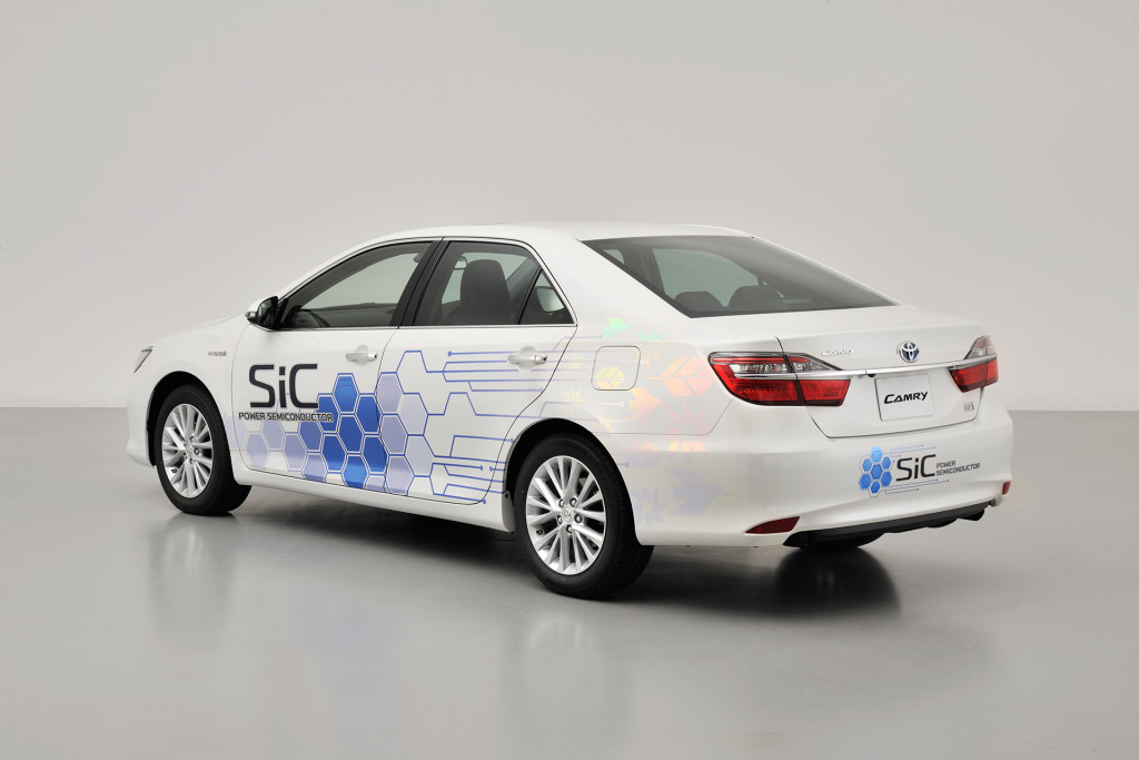
Using a “Camry” hybrid prototype and a fuel cell bus, Toyota Motor Corporation will bring a brand new technology to the streets of Japan for testing this year. The tests will evaluate the performance of silicon carbide (SiC) power semiconductors, which could lead to significant efficiency improvements in hybrids and other vehicles with electric powertrains.

SiC Silicon Carbide Hybrid camry toyota EV HEV electric vehicle hybrid car

Test vehicles and period

In the Camry hybrid prototype, Toyota is installing SiC power semiconductors (transistors and diodes) in the PCU’s internal voltage step-up converter and the inverter that controls the motor. Data gathered will include PCU voltage and current as well as driving speeds, driving patterns, and conditions such as outside temperature. By comparing this information with data from silicon semiconductors currently in use, Toyota will assess the improvement to efficiency achieved by the new SiC power semiconductors. Road testing of the Camry prototype will begin (primarily in Toyota City) in early February 2015, and will continue for about one year.

Similarly, on January 9, 2015, Toyota began collecting operating data from a fuel cell bus currently in regular commercial operation in Toyota City. The bus features SiC diodes in the fuel cell voltage step-up converter, which is used to control the voltage of electricity from the fuel cell stack.

Data from testing will be reflected in development, with the goal of putting the new SiC power semiconductors into practical use as soon as possible.

“Taking into account the increasing challenges IGBT technology is facing, we are very pleased to present a package that answers the needs of our industry both for today and for the foreseeable future.”

Infineon Technologies AG today announced the launch of two new power module platforms designed to improve the performance of high-voltage IGBTs in voltage classes from 1200V up to 6.5kV. To make the benefits of the new module broadly available, Infineon is offering a royalty-free license of the design to all providers of IGBT power modules. First products using the platform concept will include the high voltage classes 3.3kV (450A%

Mitsubishi Electric corporation announced today it will begin work on the development of standardized-package high-power semiconductor modules for use in heavy industry, including traction and electric-power applications, aiming to offer an optimal design for energy savings and high efficiency in high-power electronics systems.

Design Concept of High-Power Module with New Package

  • Common package design for modules of up to 6.5kV rating
  • Simple, easy parallel connection realizes various current ratings
  • Package compatibility with products of Infineon Technologies AG (Germany)


The first products to incorporate the new design platform will be for the high-voltage classes 3.3kV (450A), 4.5kV (400A) and 6.5kV (275 A). The standardized package will measure 100mm x 140mm x 40mm.

High-power modules are key devices used in power systems of between several kW and several MW. High-current modules with maximum ratings of 6.5 kV exist already. The industrial power market requires diverse modules suited to various current and voltage ratings according to each system’s power-conversion capacity. Products with compatible package dimensions from multiple manufacturing sources are also in demand.

Mitsubishi Electric intends to satisfy these market demands with its new high-power modules. Further details will be introduced in power electronics-related exhibitions, such as TECHNO-FRONTIER in Japan and Power Conversion Intelligent Motion Europe in Germany, both of which will be held in May 2015.